Module, Wireless Charging Pad: Installation: Installation
 Courtesy of CHRYSLER GROUP, LLC
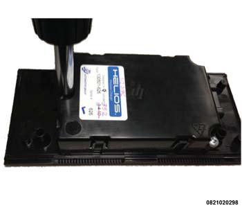
- Attach wireless charging module to the upper tray with three screws using #S2 screwdriver.
 Courtesy of CHRYSLER GROUP, LLC
 Courtesy of CHRYSLER GROUP, LLC
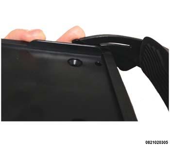
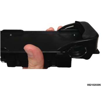
- Attach one end stop by pivoting it into the tray.
 Courtesy of CHRYSLER GROUP, LLC
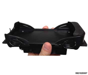
- Repeat step 2 to install the other end stop to the tray.
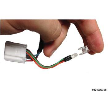 Courtesy of CHRYSLER GROUP, LLC
- Insert the LED into the LED lens.
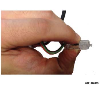 Courtesy of CHRYSLER GROUP, LLC
- Squeeze on the LED lens retaining clips to make sure they are engaged. Tug on the LED harness to confirm the LED is seated.
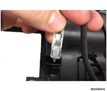 Courtesy of CHRYSLER GROUP, LLC
- Insert the LED Lens into the Lower Tray ensuring that the round portion of the Lens faces the opening in the Lower Tray.
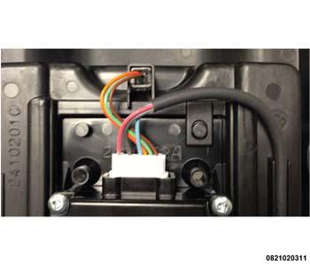 Courtesy of CHRYSLER GROUP, LLC
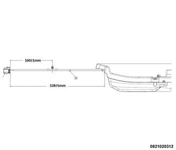
- Place upper tray assembly into lower tray and insert the Tyco connector into module and wire harness in the channel ensuring the routing of the harness mimics the related graphic exactly.
 Courtesy of CHRYSLER GROUP, LLC
- The distance from the connector to channel entry point has to be 88mm±3mm. The distance from the exit of the tray to connector needs to be exactly 328±5mm.
 Courtesy of CHRYSLER GROUP, LLC
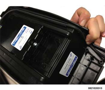
- Ensure also to hold down the harness in the channel at the back of the part while putting on bottom cover.
 Courtesy of CHRYSLER GROUP, LLC
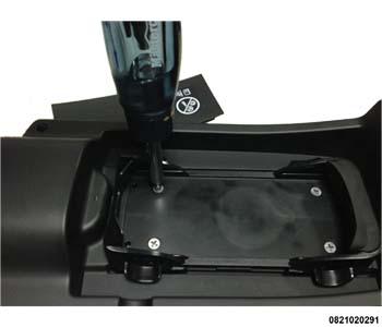
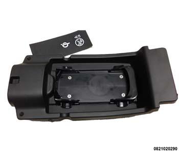
- Attach bottom cover to upper tray with four screws using Phillips #2 screwdriver.
 Courtesy of CHRYSLER GROUP, LLC
- Ensure end stops are at the full out positions.
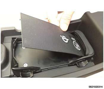 Courtesy of CHRYSLER GROUP, LLC
- Wedge the edge of the anti-slip mat under the rigid end stop bumper.
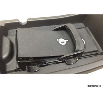 Courtesy of CHRYSLER GROUP, LLC
- Slide the Bumper over the mat.
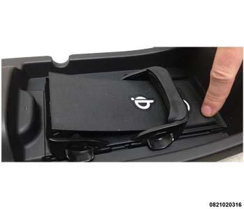 Courtesy of CHRYSLER GROUP, LLC
- Push down the two pins into blind bosses.
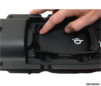 Courtesy of CHRYSLER GROUP, LLC
- Push down the two pins on the other side of the mat into blind bosses to fully seat anti slip mat.
- Reconnect the negative battery cable.