Manifold Pressure/Vacuum Sensor: Testing and Inspection
MANIFOLD ABSOLUTE PRESSURE (MAP) SENSOR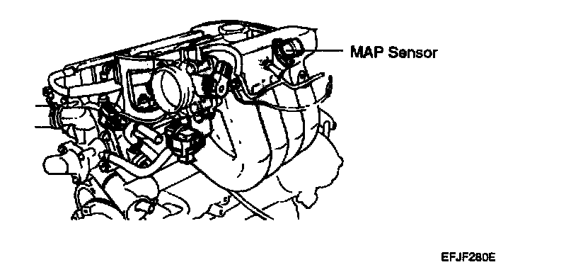
The Manifold Absolute Pressure (MAP) Sensor converts intake manifold pressure into a voltage signal. ECM uses this signal to determine the condition of the Exhaust Gas Recirculation (EGR).
Circuit Diagram (MAP):
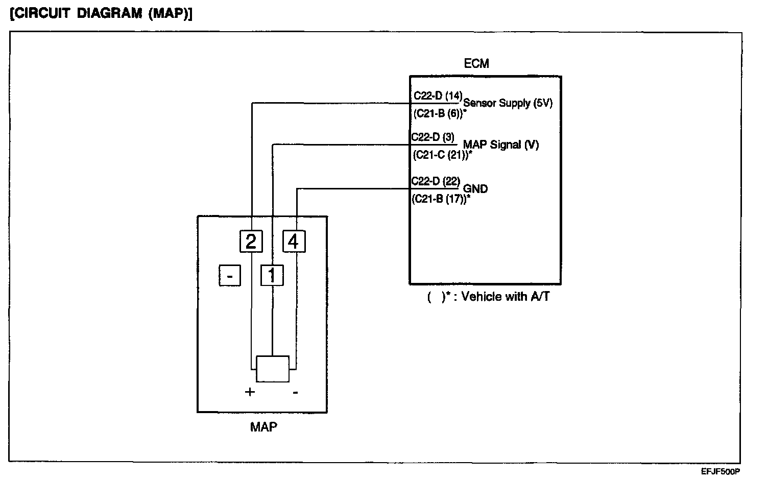
CIRCUIT DIAGRAM (MAP)
Harness Connector:
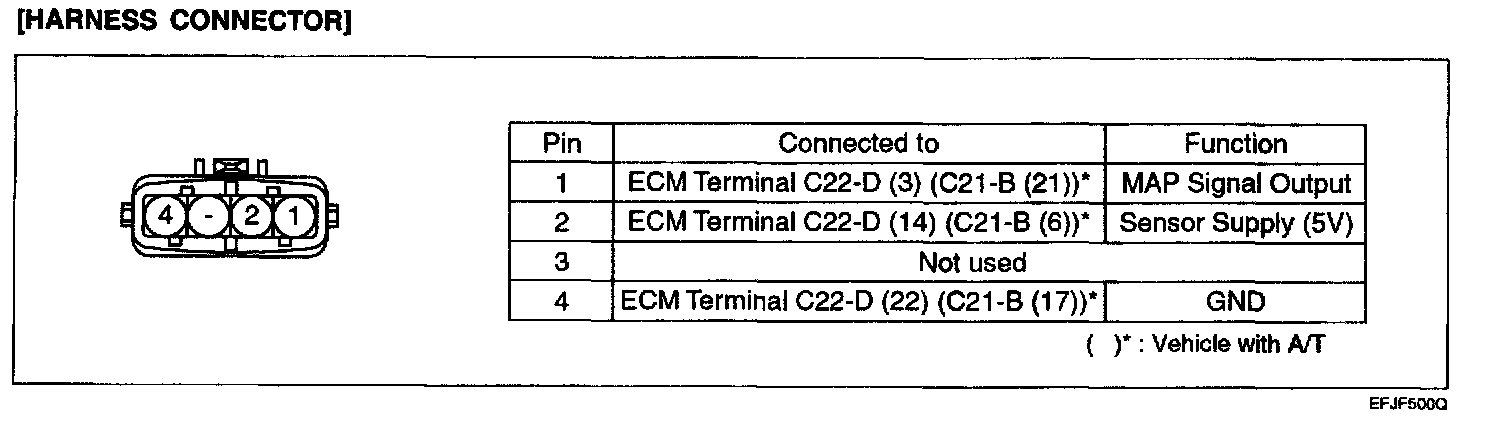
HARNESS CONNECTOR
Using Hi-Scan (PRO):
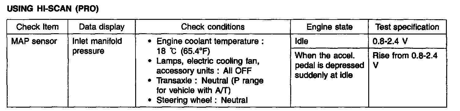
USING HI-SCAN (PRO)
Troubleshooting Procedures (MAP Sensor):
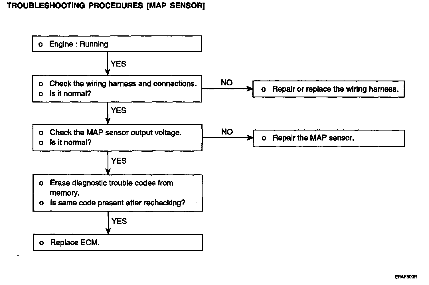
TROUBLESHOOTING PROCEDURES (MAP SENSOR)
SENSOR INSPECTION
1. Connect the voltmeter between 1 and 4 of MAP sensor connector.
Terminal 4: MAP sensor ground
Terminal 1: MAP sensor output
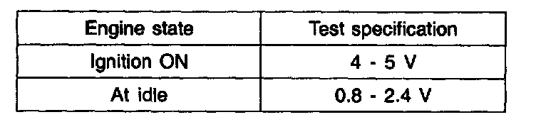
2. Measure the voltage of terminals.
3. If the voltage deviates from the standard value, replace the MAP sensor assembly.
TROUBLESHOOTING HINTS
The MIL (Malfunction Indicator Lamp) is ON (or OFF) or the DTC (Diagnostic Trouble Code) is displayed on the HI-SCAN under the following conditions;
1. When the manifold pressure is 4.5 V or more for 4 second.
2. When the manifold pressure is 0.2 V or lower for 4 second.
Harness Inspection Trocedures (MAP):
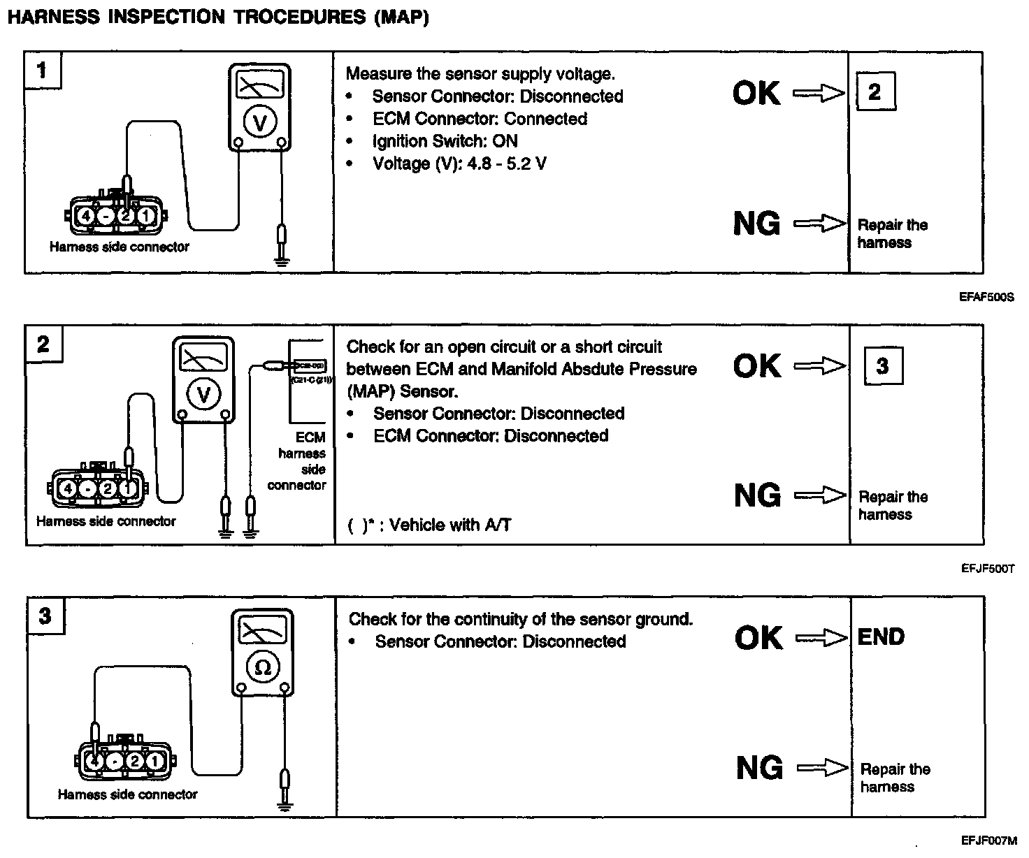
HARNESS INSPECTION PROCEDURES (MAP)