Power Circuits
- Ensure ignition is OFF. Using DVOM, check for battery voltage between chassis ground and PCM Keep Alive Memory Power (KAPWR) terminal No. 55. See Fig 1. If battery voltage is present, go to next step. If battery voltage is not present, check for open in KAPWR circuit or fuse No. 2 (5-amp), located in central junction box. See ENGINE PERFORMANCE
in SYSTEM WIRING DIAGRAMS - F150 article in ELECTRICAL.
- Turn ignition on. Using DVOM, check for battery voltage between chassis ground and VPWR at PCM connector terminals No. 71 and 97. If battery voltage is not present, power is not being supplied from PCM power relay. See TEST B: EEC-V POWER RELAY
under SYSTEM TESTS in SELF-DIAGNOSTICS - CNG, FLEX-FUEL & GASOLINE article.
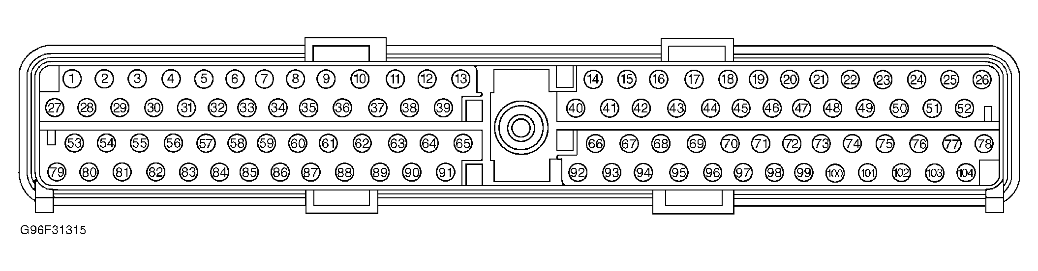 Courtesy of FORD MOTOR CO.