Connector Identification
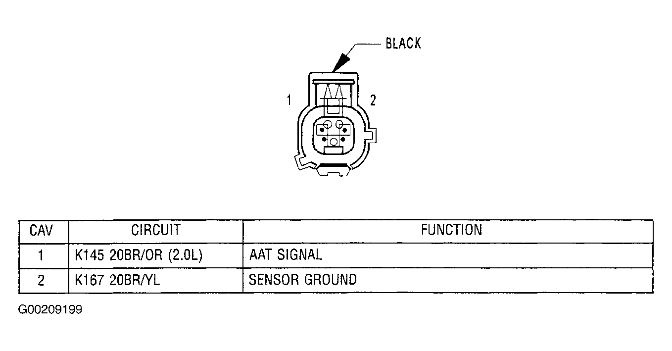 Courtesy of CHRYSLER CORP.
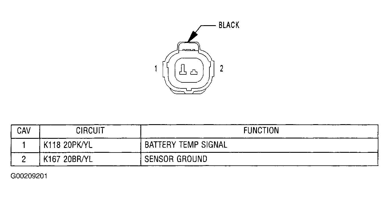 Courtesy of CHRYSLER CORP.
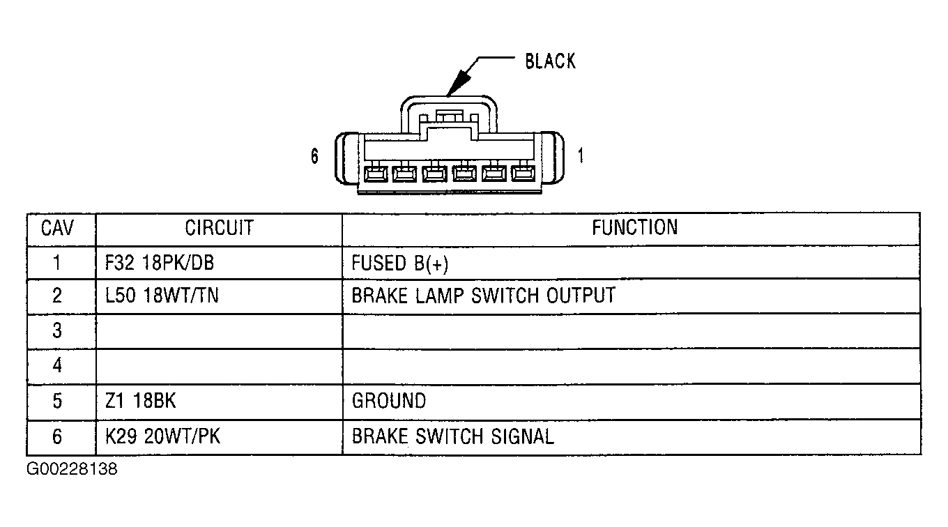 Courtesy of CHRYSLER CORP.
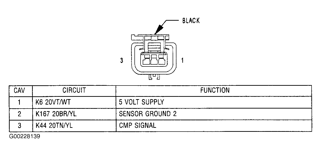 Courtesy of CHRYSLER CORP.
 Courtesy of CHRYSLER CORP.
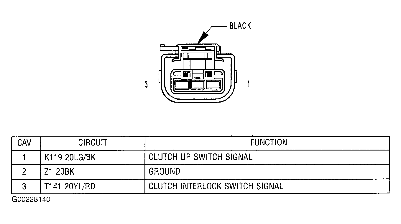 Courtesy of CHRYSLER CORP.
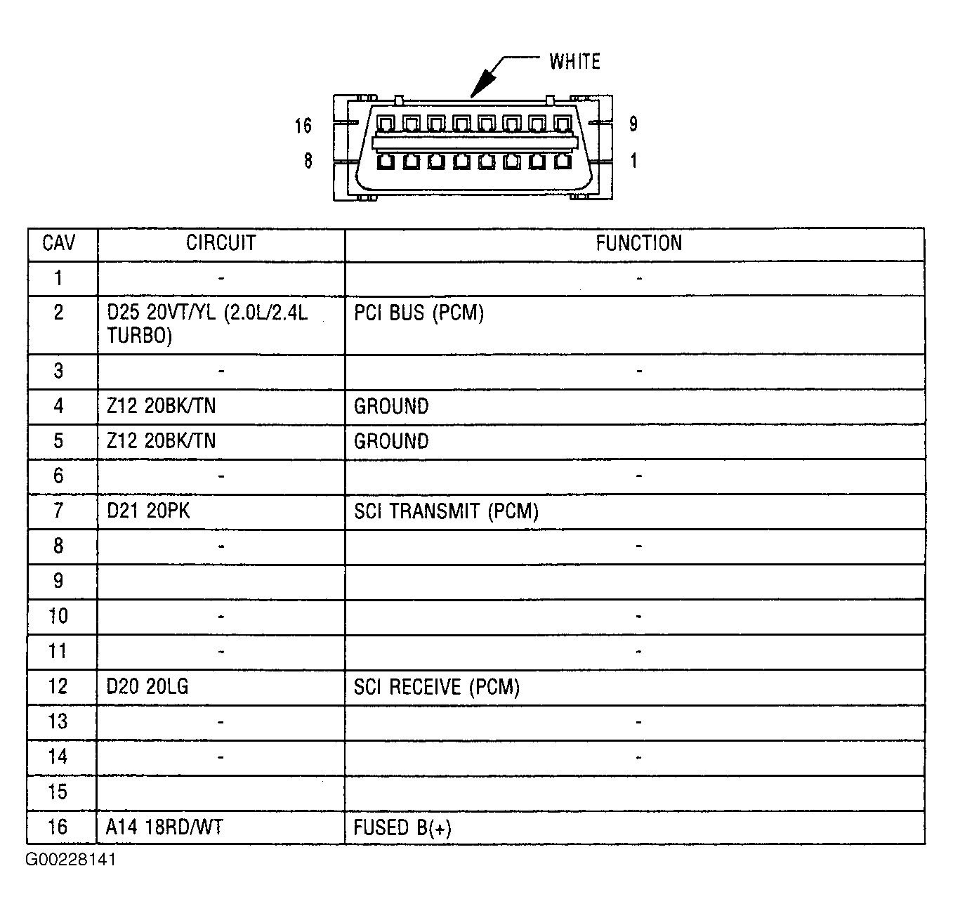 Courtesy of CHRYSLER CORP.
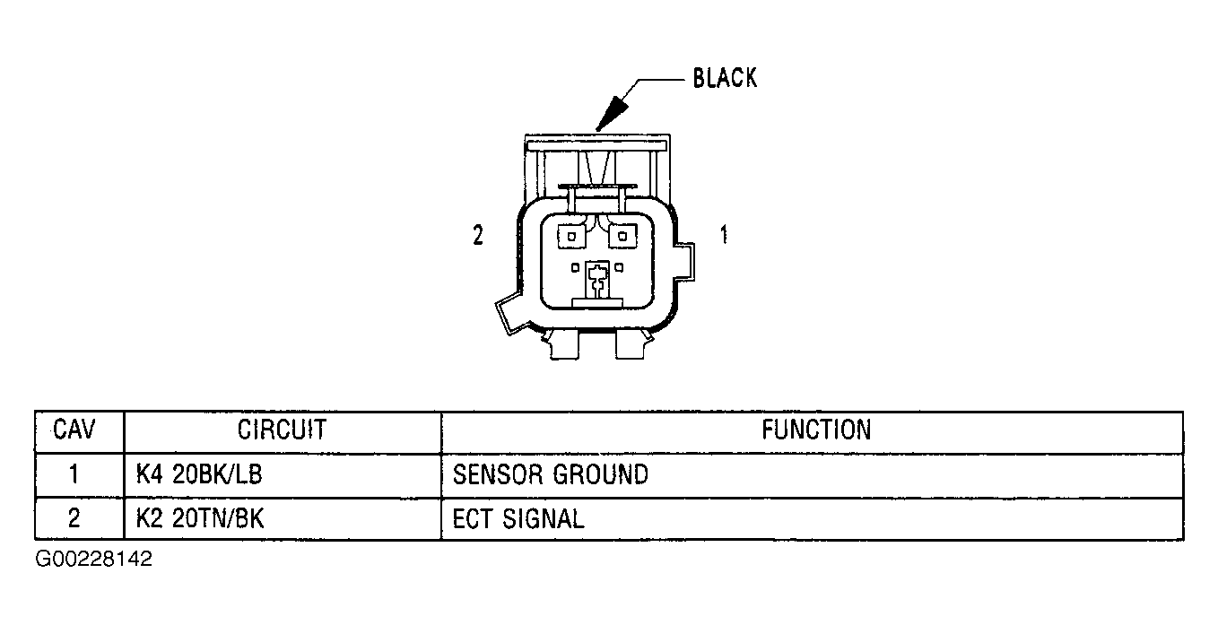 Courtesy of CHRYSLER CORP.
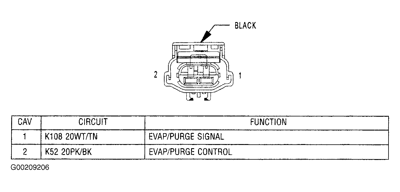 Courtesy of CHRYSLER CORP.
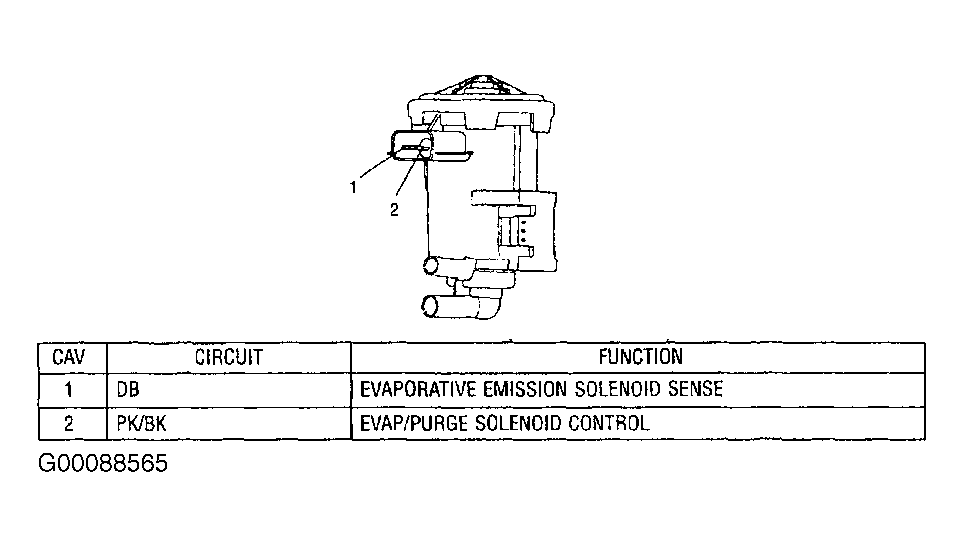 Courtesy of DAIMLERCHRYSLER CORP.
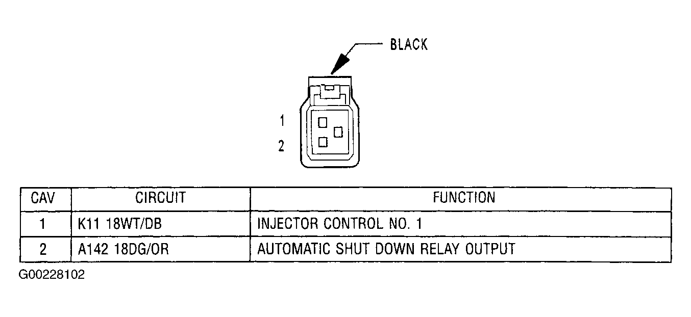 Courtesy of CHRYSLER CORP.
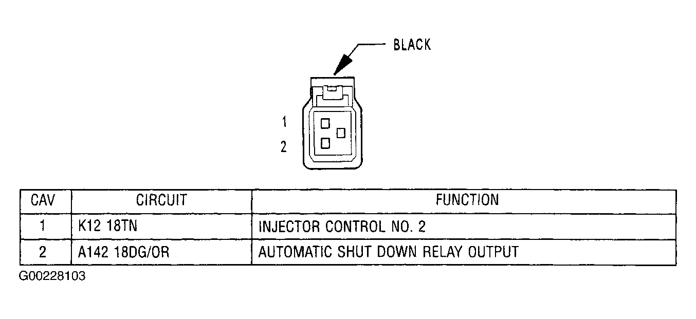 Courtesy of CHRYSLER CORP.
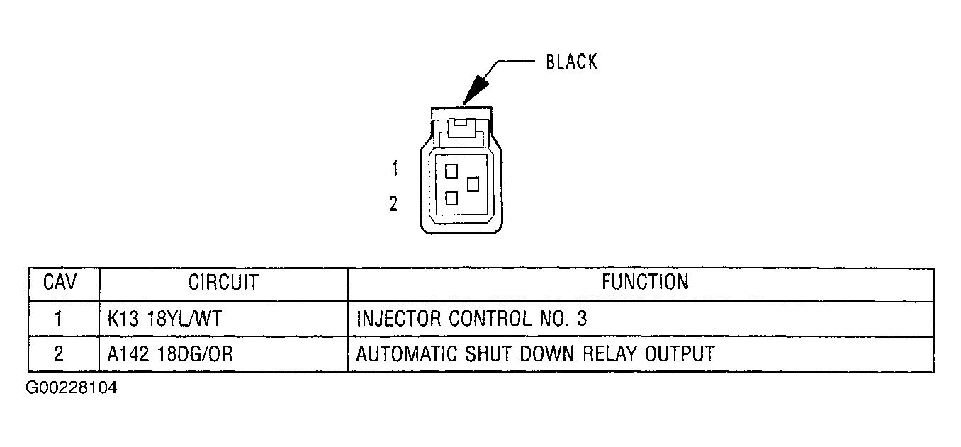 Courtesy of CHRYSLER CORP.
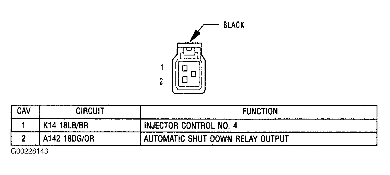 Courtesy of CHRYSLER CORP.
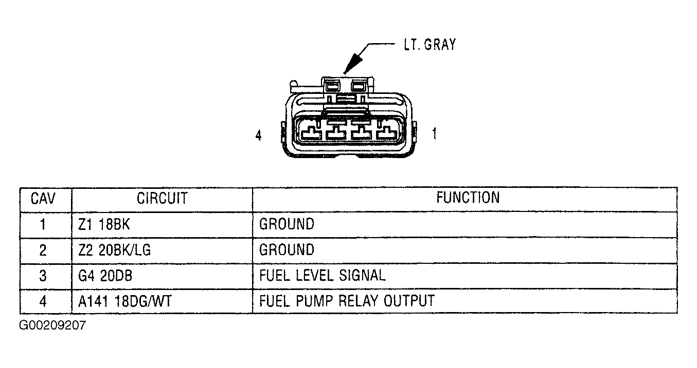 Courtesy of CHRYSLER CORP.
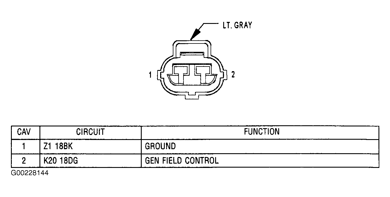 Courtesy of CHRYSLER CORP.
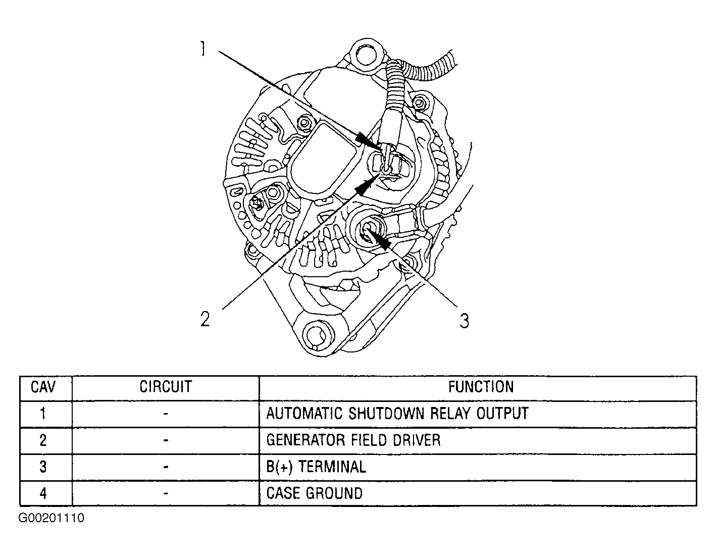 Courtesy of CHRYSLER CORP.
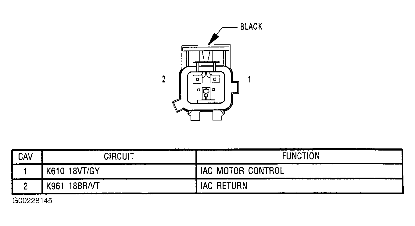 Courtesy of CHRYSLER CORP.
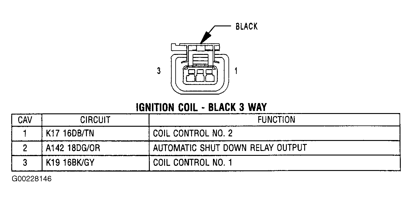 Courtesy of CHRYSLER CORP.
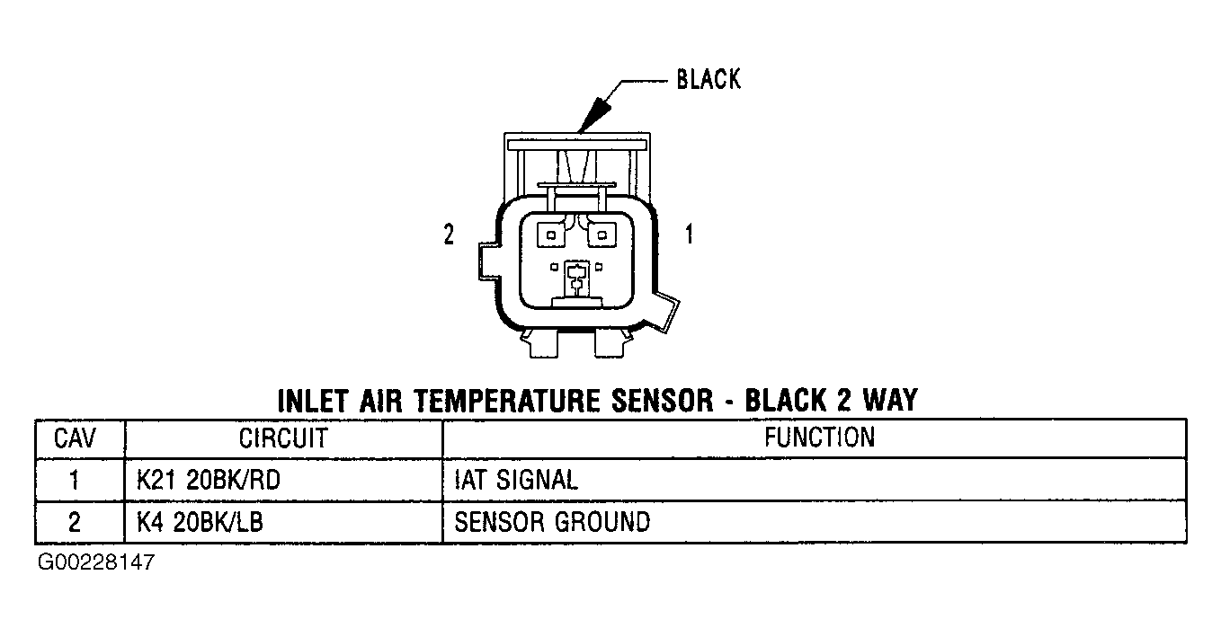 Courtesy of CHRYSLER CORP.
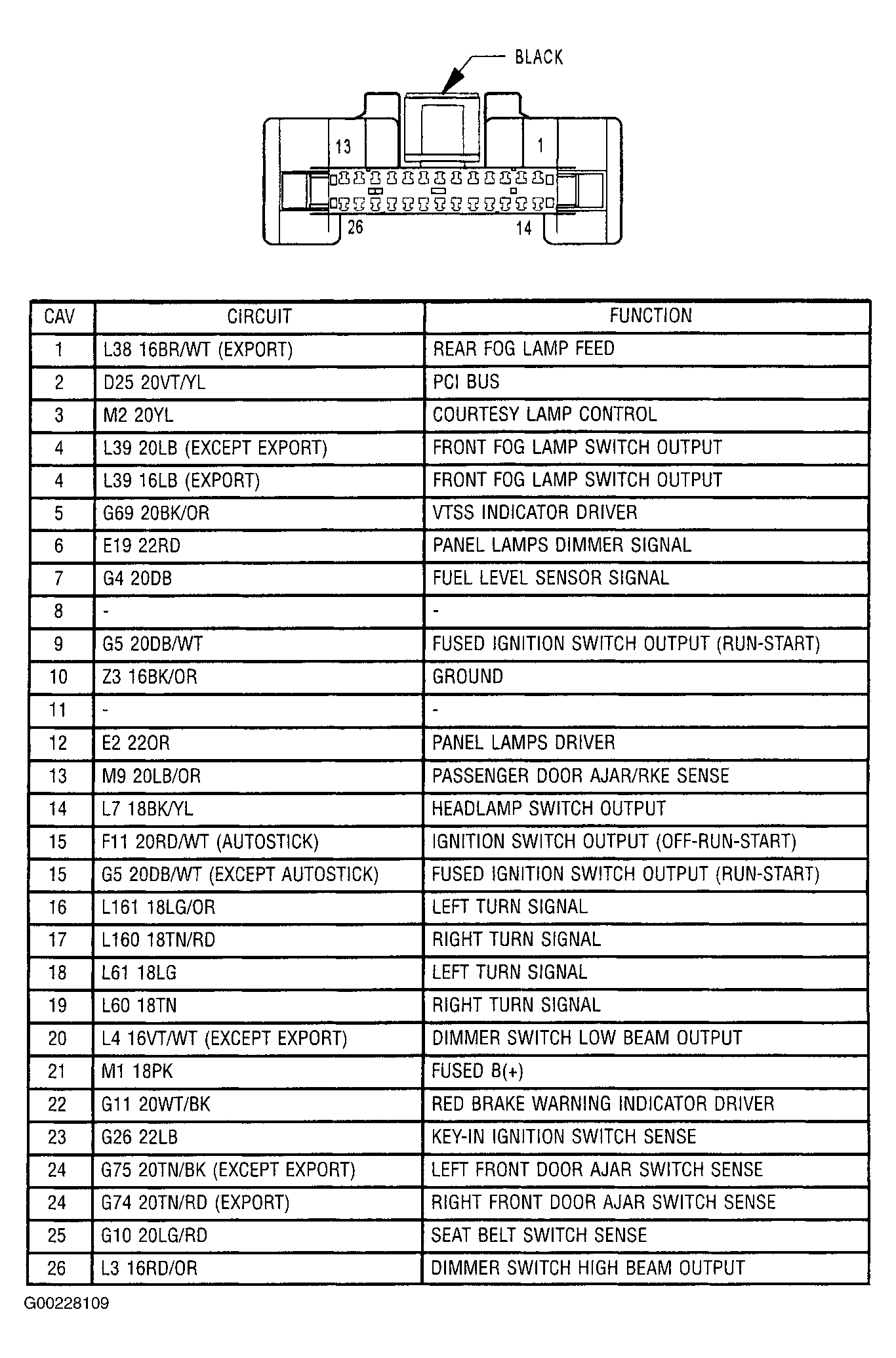 Courtesy of CHRYSLER CORP.
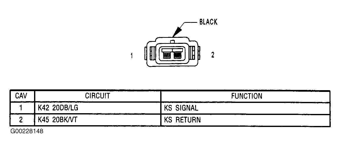 Courtesy of CHRYSLER CORP.
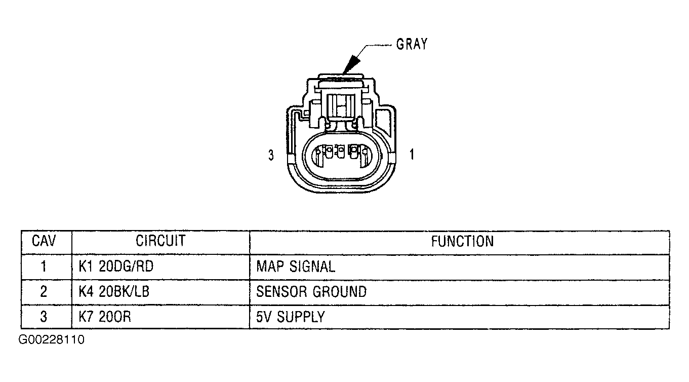 Courtesy of CHRYSLER CORP.
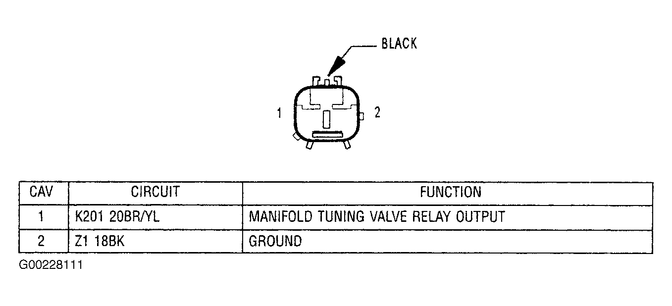 Courtesy of CHRYSLER CORP.
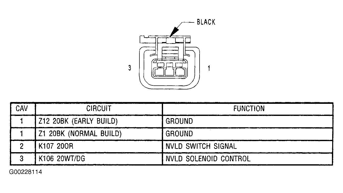 Courtesy of CHRYSLER CORP.
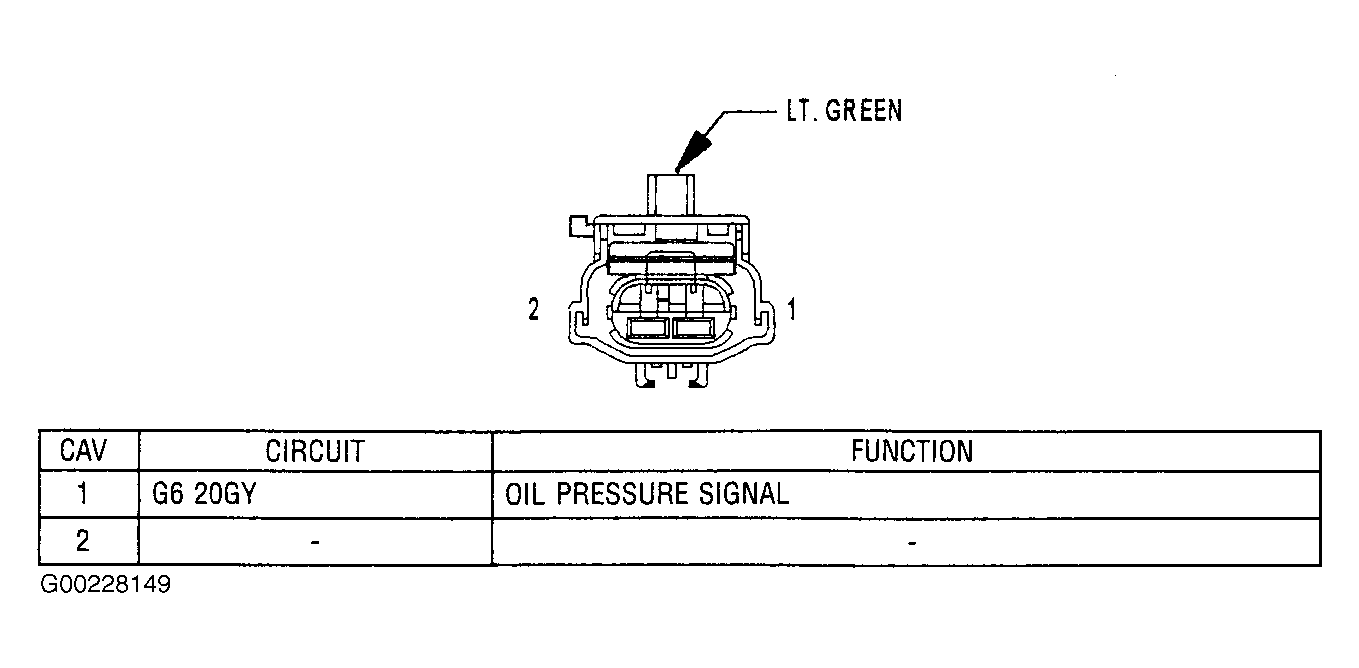 Courtesy of CHRYSLER CORP.
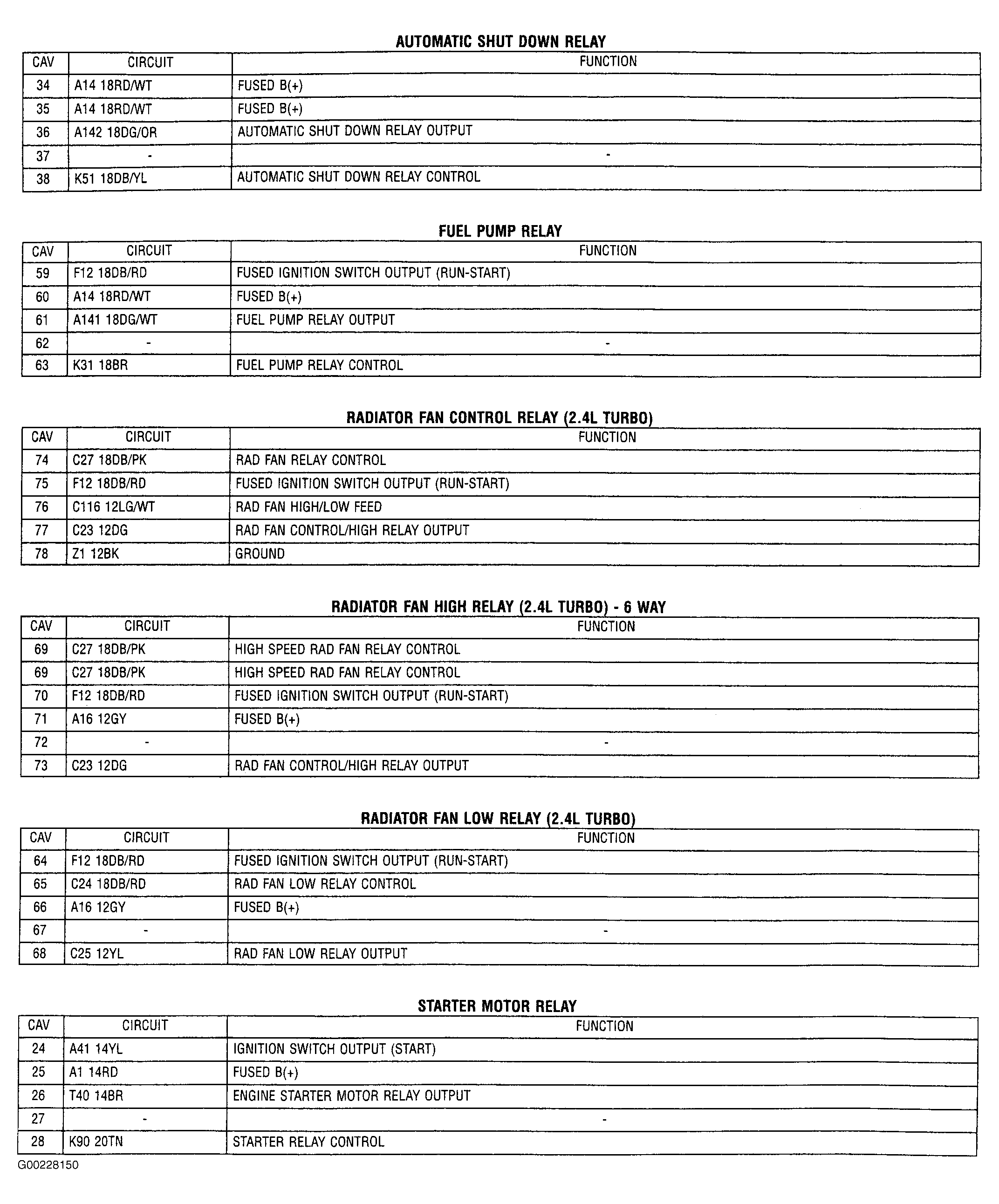 Courtesy of CHRYSLER CORP.
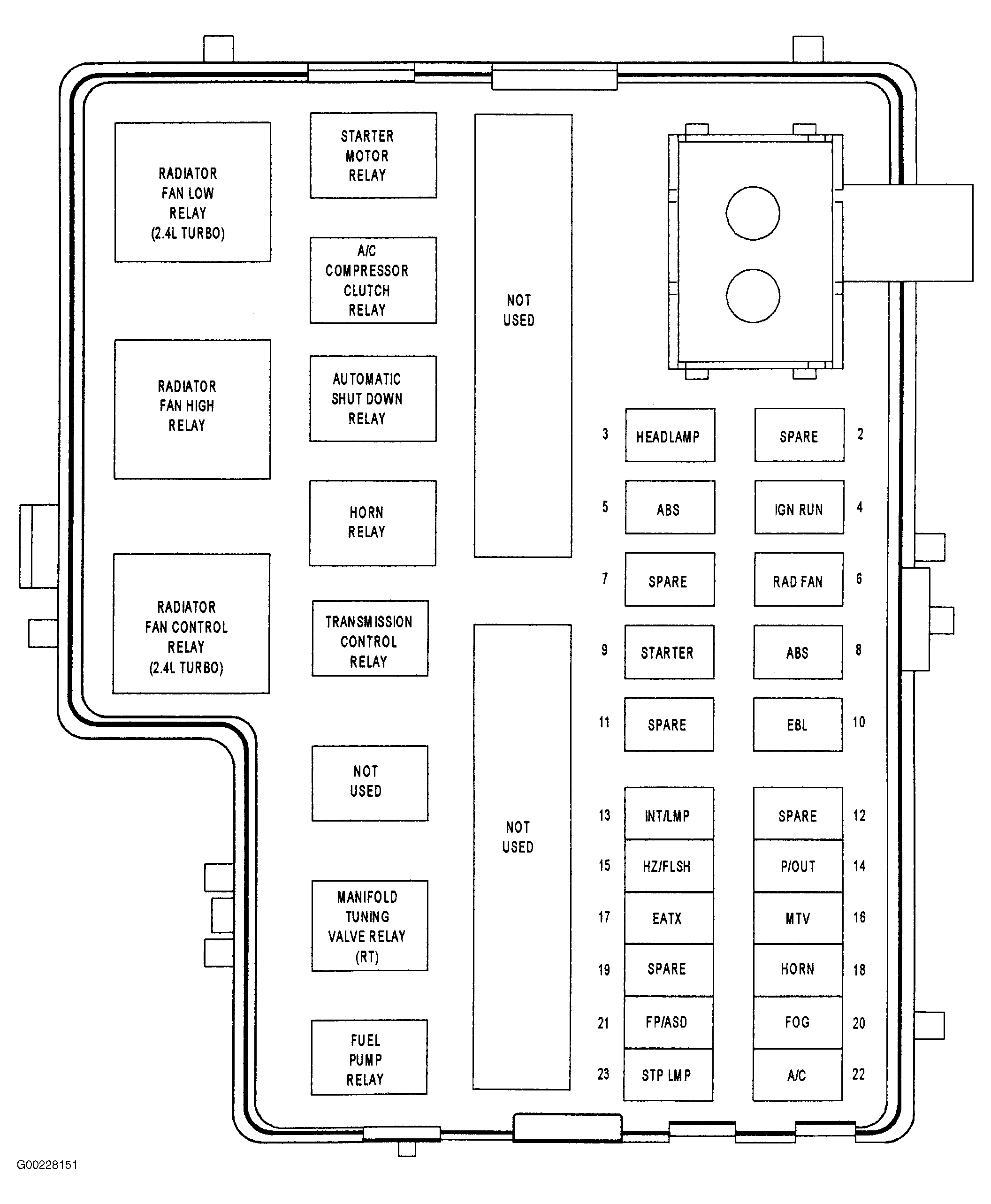 Courtesy of CHRYSLER CORP.
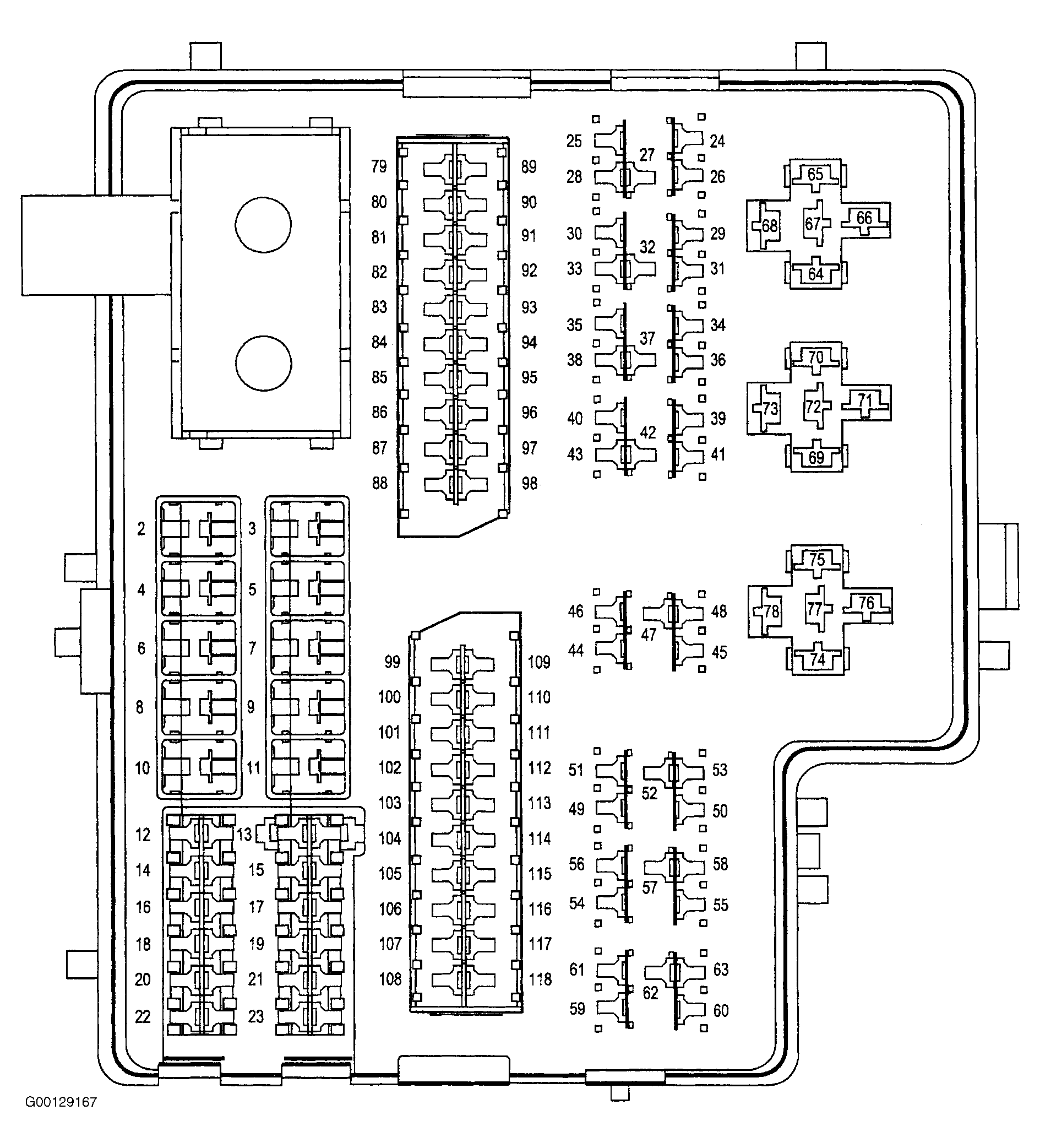 Courtesy of DAIMLERCHRYSLER CORP.
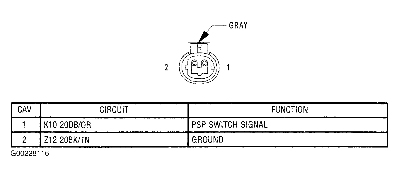 Courtesy of CHRYSLER CORP.
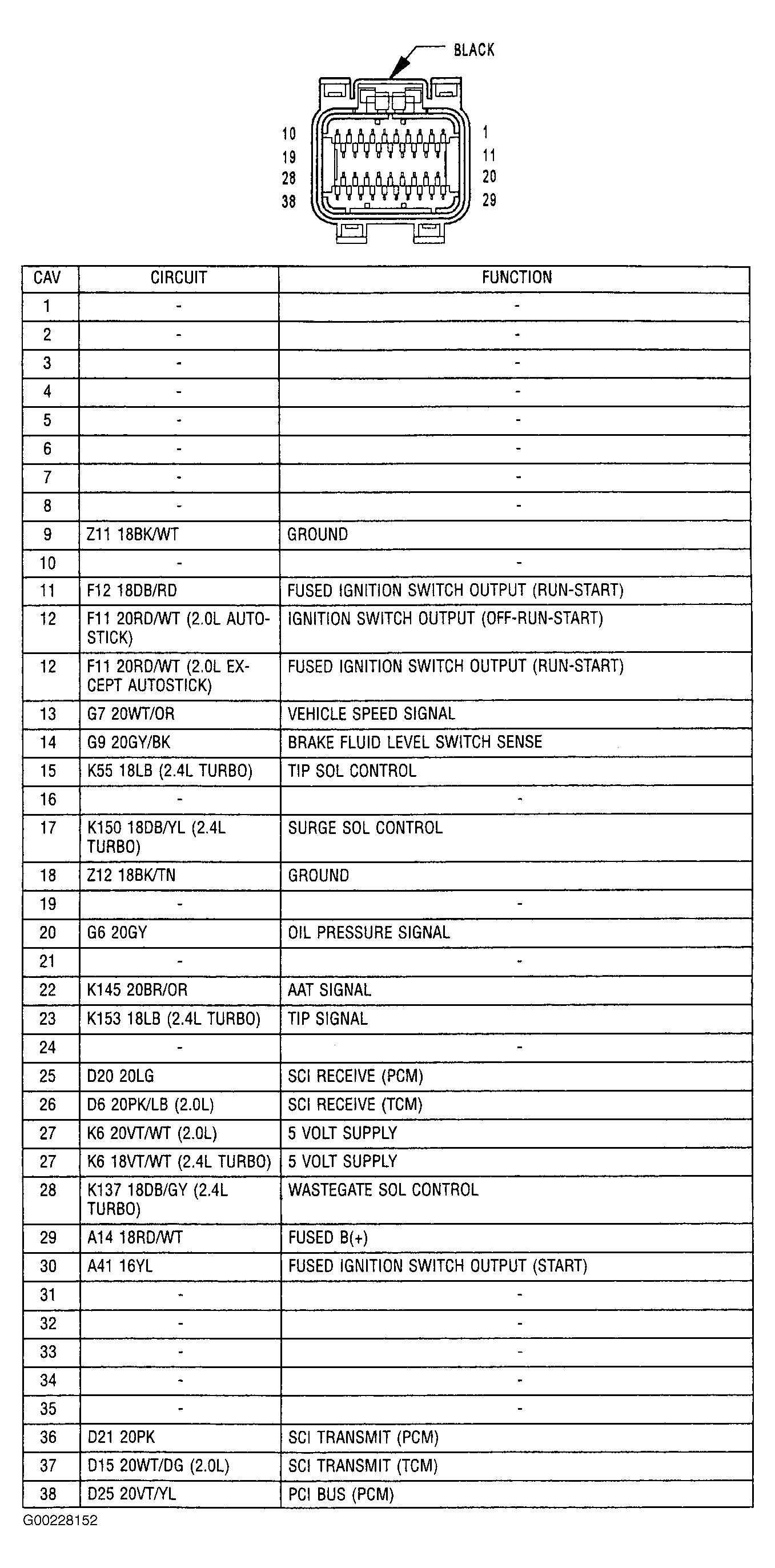 Courtesy of CHRYSLER CORP.
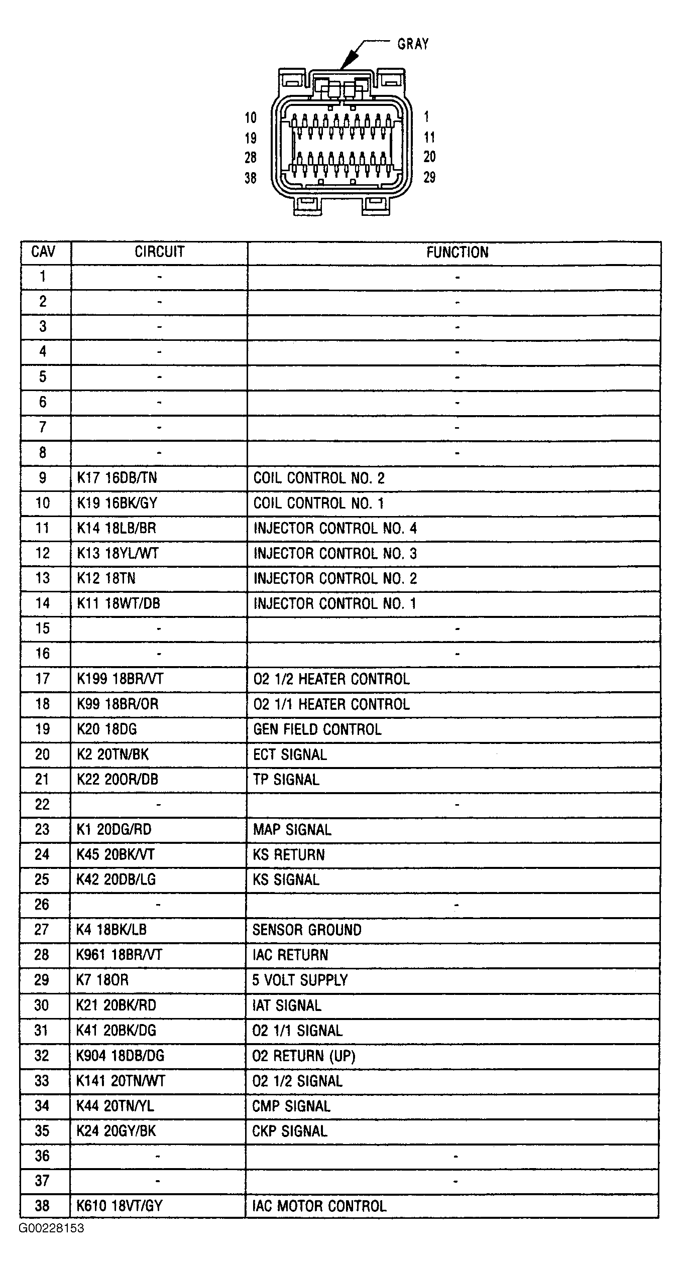 Courtesy of CHRYSLER CORP.
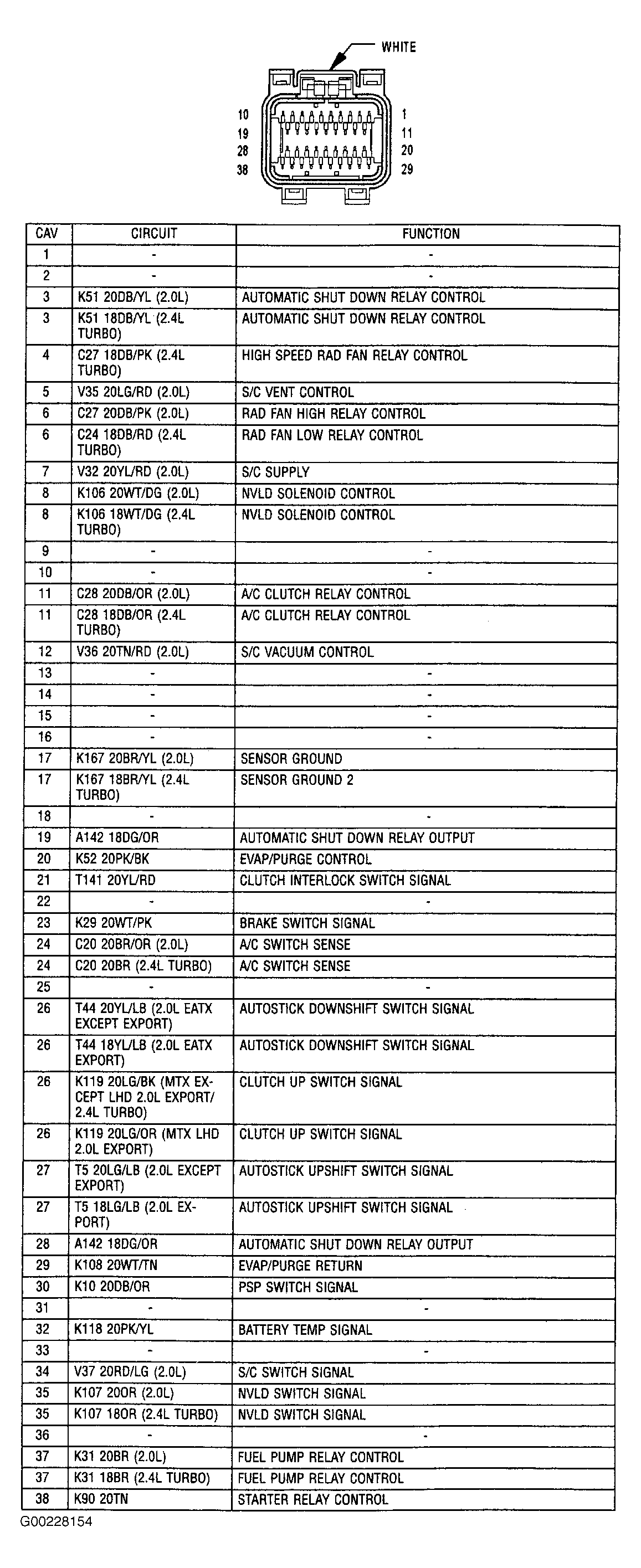 Courtesy of CHRYSLER CORP.
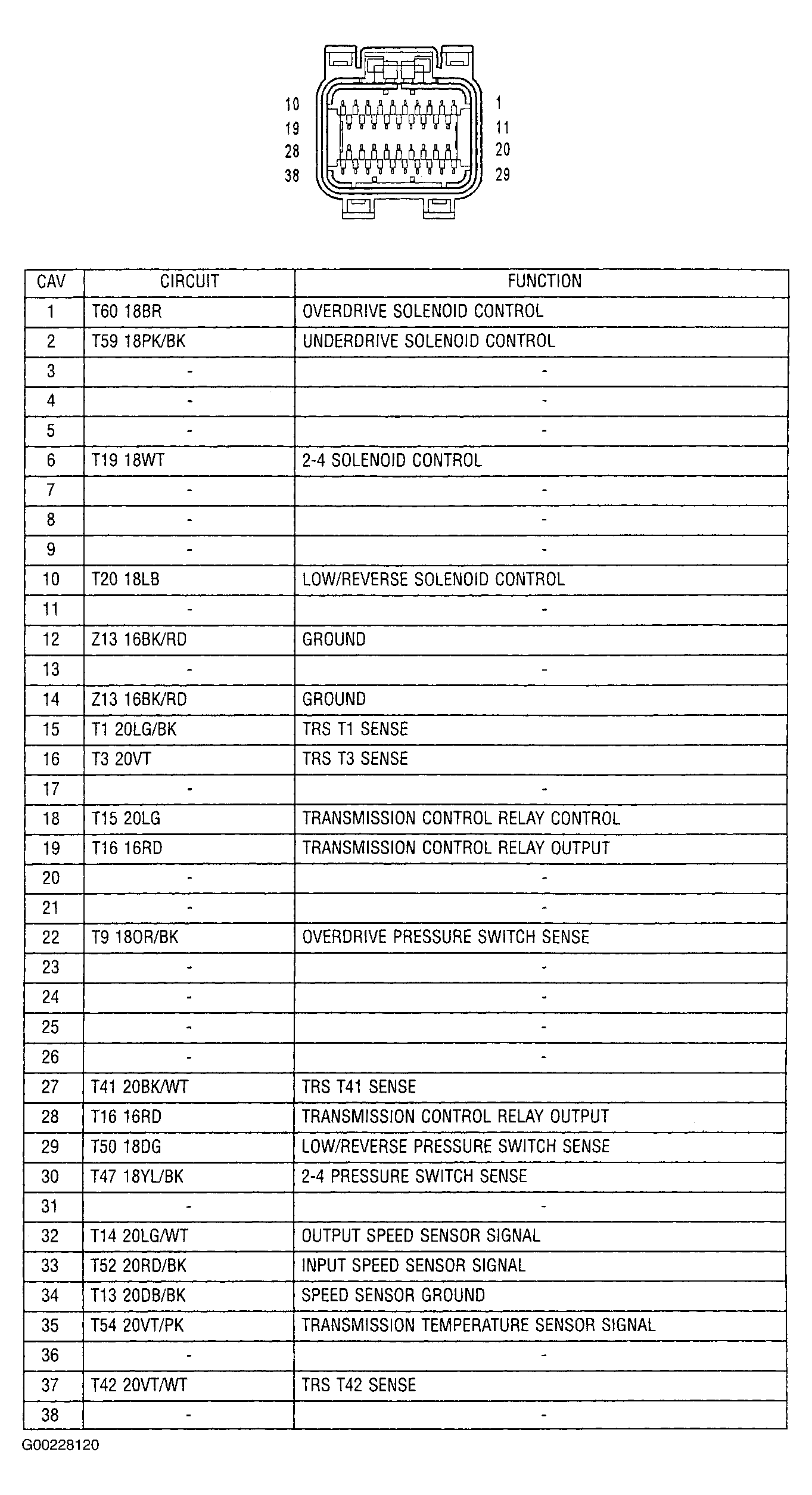 Courtesy of CHRYSLER CORP.
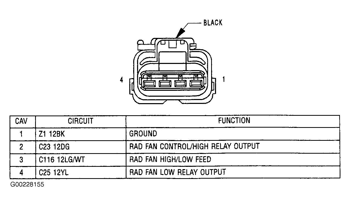 Courtesy of CHRYSLER CORP.
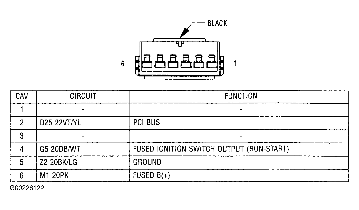 Courtesy of CHRYSLER CORP.
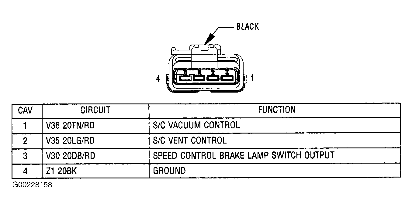 Courtesy of CHRYSLER CORP.
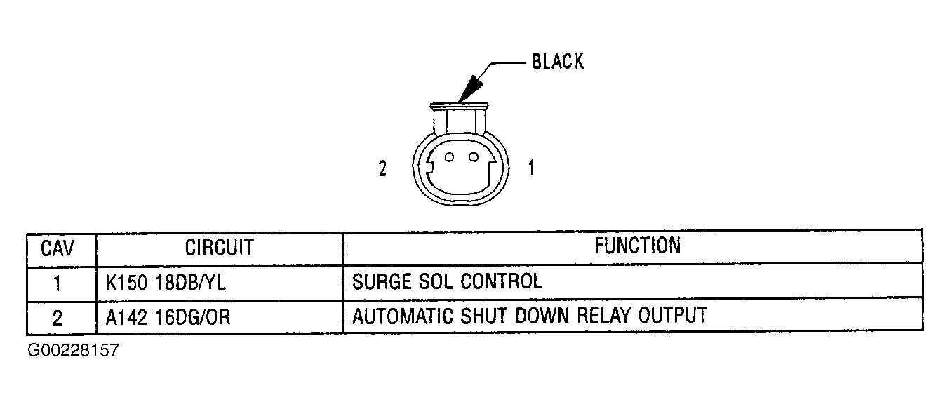 Courtesy of CHRYSLER CORP.
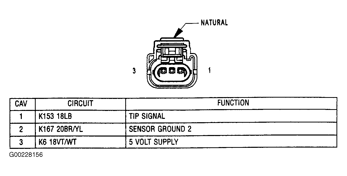 Courtesy of CHRYSLER CORP.
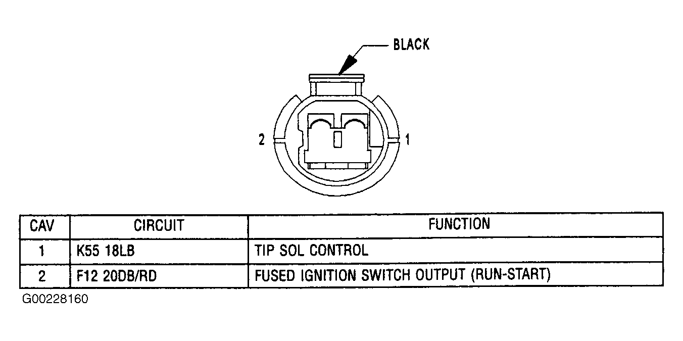 Courtesy of CHRYSLER CORP.
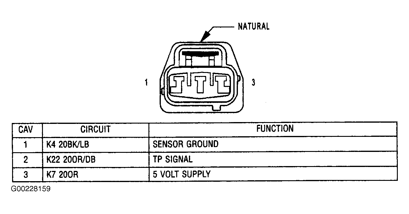 Courtesy of CHRYSLER CORP.
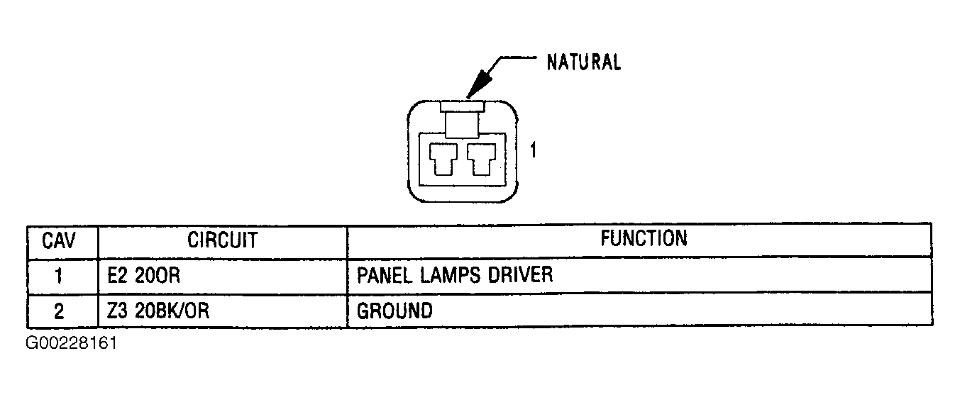 Courtesy of CHRYSLER CORP.
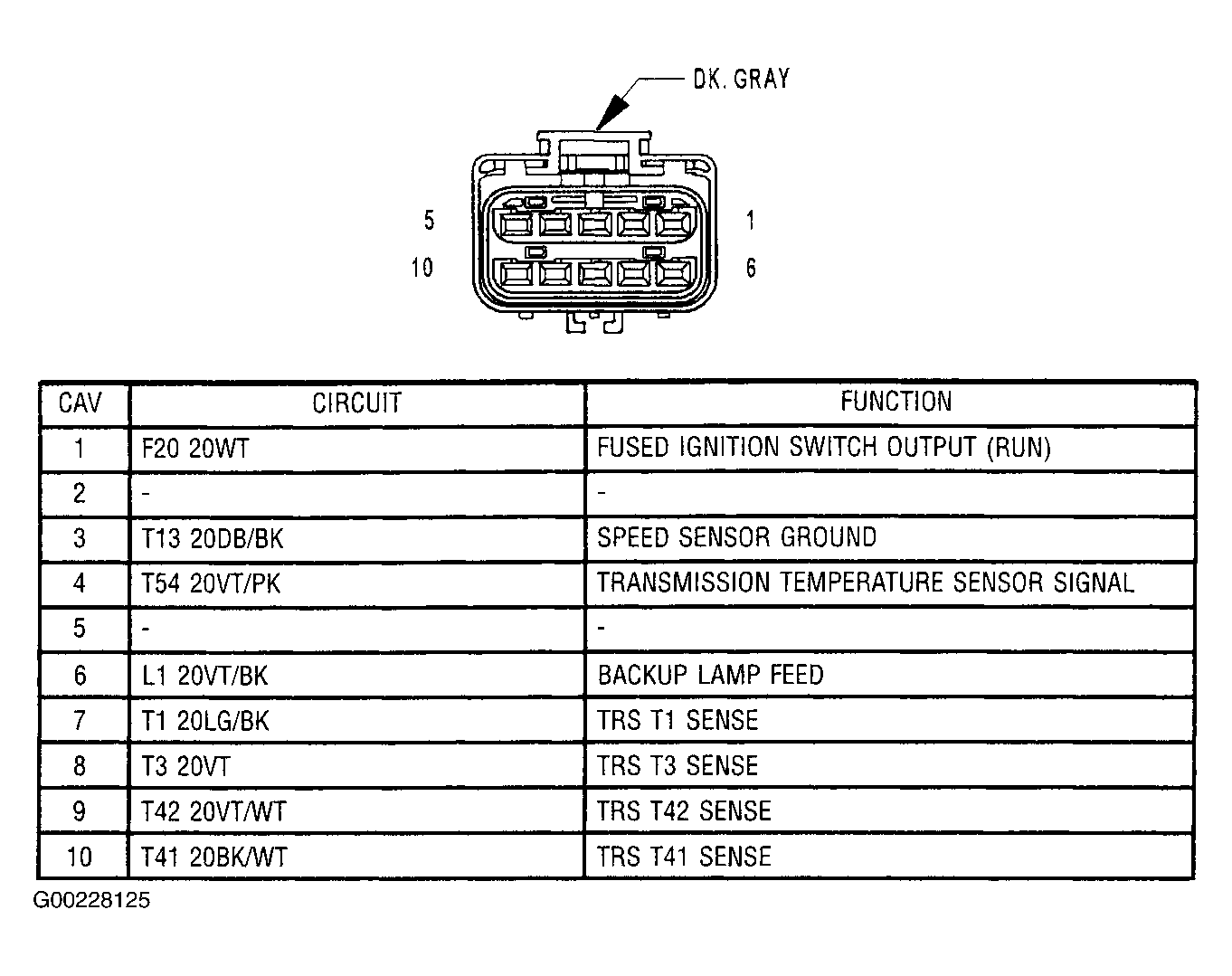 Courtesy of CHRYSLER CORP.
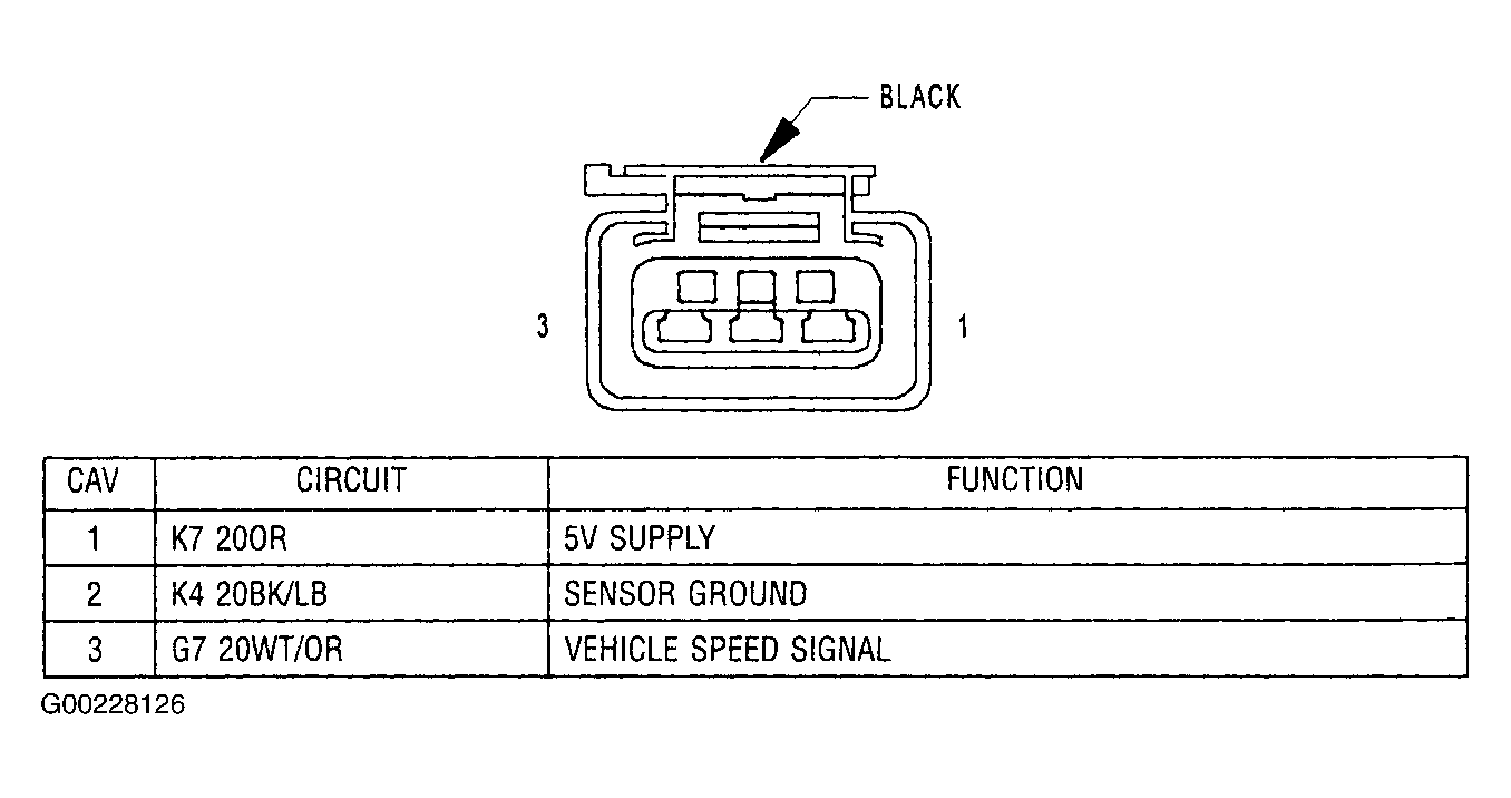 Courtesy of CHRYSLER CORP.
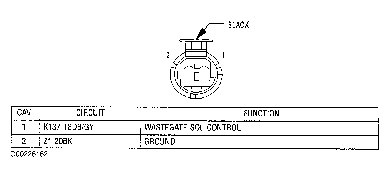 Courtesy of CHRYSLER CORP.
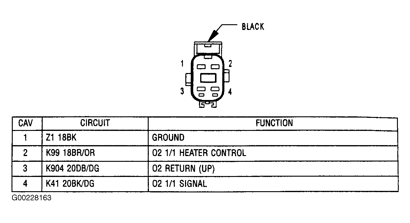 Courtesy of CHRYSLER CORP.
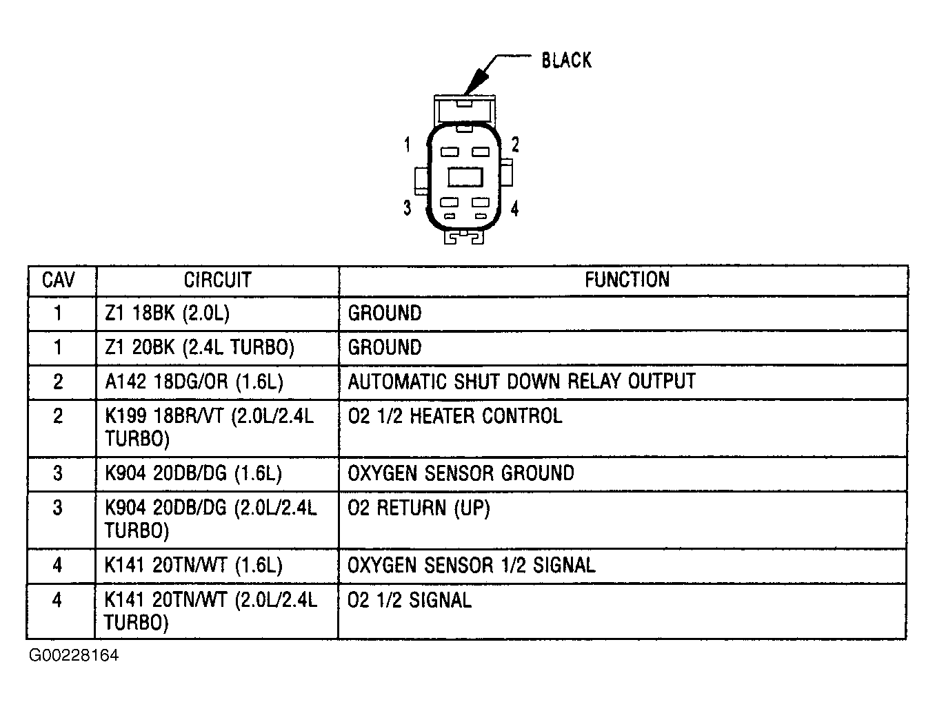 Courtesy of CHRYSLER CORP.